1.0 Introduction
The Industrial Internet of Things (IIoT) consists of networked devices creating systems that can monitor, collect, exchange, and analyze data to enable smarter, faster business decisions for industrial companies. The benefits of applying IIoT approaches to industrial business problems is huge as even a small percentage improvement in efficiency, time, capital expenditure, asset allocation translates into significant savings and/or revenue enhancement. IIoT solutions have demonstrated these types of percentage improvements. However, to implement an IIoT solution requires an understanding of their architecture and design.
The purpose of this document is to provide that understanding for IIoT monitoring systems. Note that IIoT systems can be used for monitoring as well as control. Of the two use cases, monitoring is generally simpler to setup and maintain. Immediate benefits of IIoT monitoring include: remote alarming of conditions, history tracking, and eliminating the time and effort of manual checking.
The rest of this document starts with a conceptual architecture for IIoT monitoring solution in Section 2.0. The conceptual architecture provides a framework for describing the design architecture options which are detailed in Section 3.0. A selection guide for choosing between options is provided in Section 4.0. The overview of the Omega Link ecosystem and product line in Section 5.0 demonstrates one instantiation of the design architecture. Section 5.0 provides a brief introduction to the topic of edge computing, which returns to the using IIoT for control vs monitoring.
The topic of IIoT security is an important one. We leave a detailed discussion for another document, but we do provide a summary of architecture-related guidance in the Appendix. The conceptual and design architectures presented (as well as Omega’s Omega Link ecosystem) incorporate security as an integral part of their structures.
2.0 Conceptual Architecture
2.1 Overview
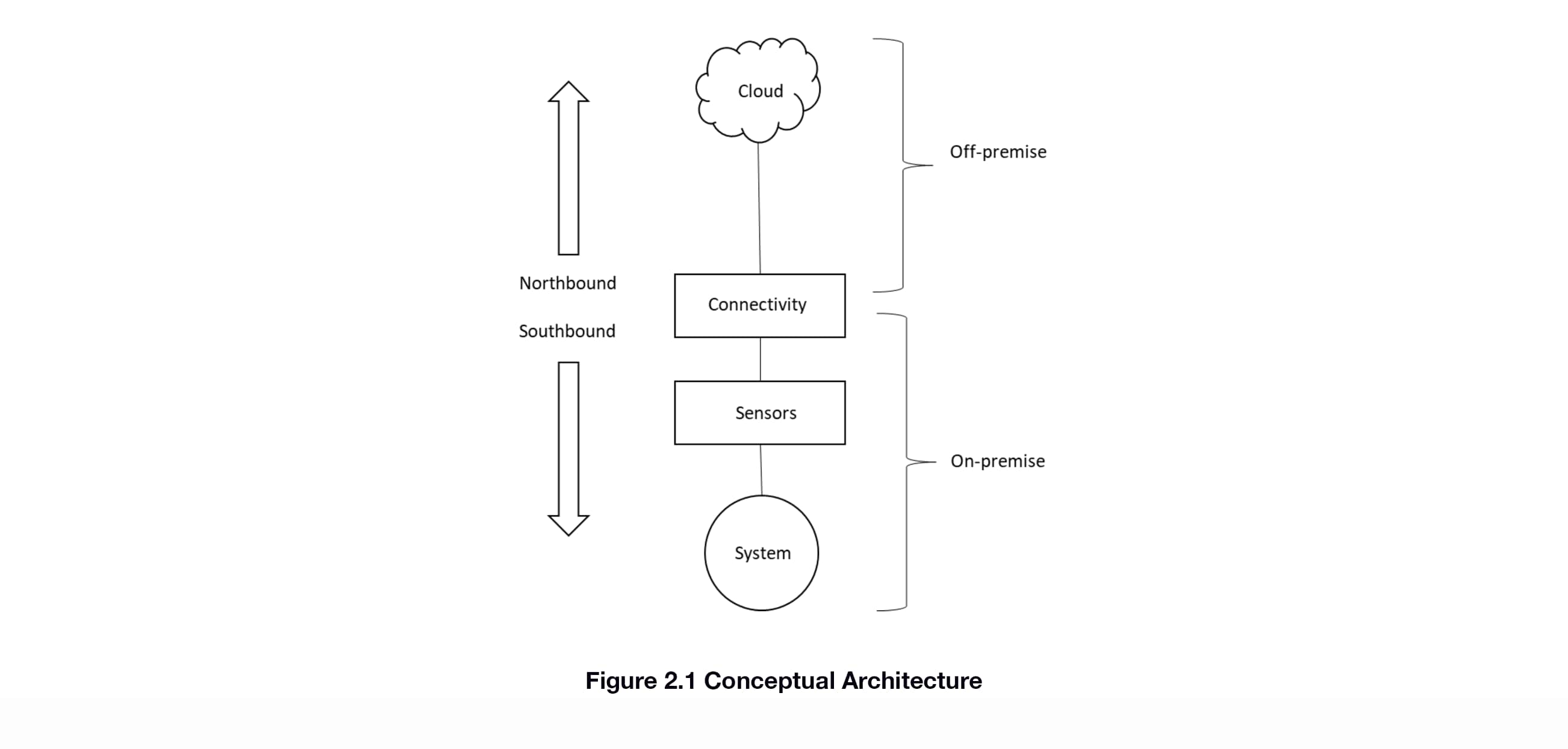
The conceptual architecture for an IIoT solution is given in Figure 2.1. A system is being monitored by one or more sensors. The system and sensors are on-premise. The information from those sensors is sent to an off-premise location in the cloud via the connectivity element. We refer to data moving from the connectivity element to the cloud as “northbound” communications and from the connectivity element to the sensors as “southbound”.
2.2 Elements
2.2.1 Cloud
The cloud is the off-premise storage and analysis location for the data coming from the sensors. It also provides secure user access to this data, typically via web browser login. Unlike on-premise storage which is typically limited to access at that location, cloud storage and analysis is available via the internet. Internet access allows for the user or users to access this data remotely via desktop computer, tablet, or mobile phone. Advanced analytics (ex: machine learning) are available as well.
2.2.2 Connectivity
Moving the information securely between the sensors and the cloud is the job of the Connectivity element. As will be seen in the next Section, this element is complex, due to the number of options available and sub-elements involved. Regardless of the complexity, the task remains the same, the secure movement of data.
2.2.3 Sensors
Sensors are the means for detecting the state of the system. The goal of the IIoT solution is to get the all-important data collected by the sensors into the cloud for further analysis and decision-making by users who are remote from the system itself.
3.0 Design Architecture
3.1 Overview
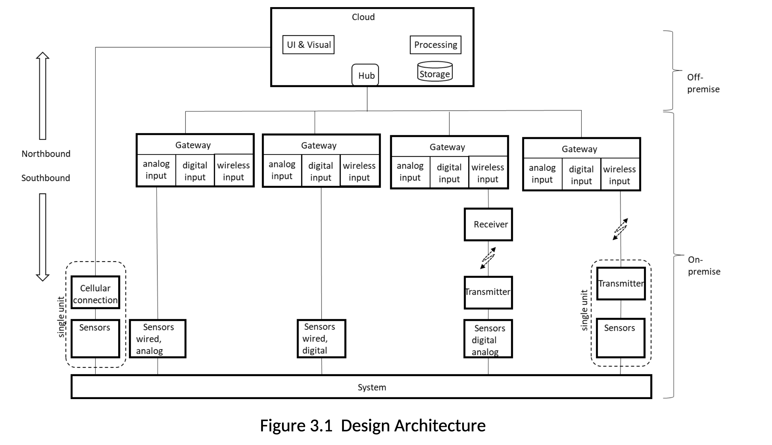
The Design Architecture (Figure 3.1) takes the Conceptual Architecture to the next level of detail by providing design options and elements for each of the major functions (cloud, connectivity, sensors). Figure 3.1 gives more detail on the cloud, connectivity, and sensors functions. Further explanation is in the subsections below.
3.2 Sensors
3.2.1 Wired vs Wireless
From an IIoT solution architecture perspective, the distinction between wired and wireless sensors is the most important attribute. Wired sensor outputs can be either analog or digital. If analog, means for converting the data into a digital format for transmission must be available further up the chain. If digital, then the protocol for moving the data must be known and supported by the connectivity solution (what we call the “southbound” connection). The digital protocol will include both the physical components (cables, connectors) as well as the software protocol. More detail is provided in the section on Connectivity: Protocols. For wireless sensors, similar to wired digital output sensors, the data has already been converted, so protocols for sending and receiving the information must be established. In addition, the physical components include wireless transmission and receiving capability.
3.2.2 Form-Factors
Form factors allow for packaging one or many sensors working across different environments and regulatory regimes. From an IIoT architecture standpoint, form factors that combine sensors with wireless transmission are important to understand. These are captured in Figure 3.1 in the “single unit” dotted line boxes. One shows a sensors that have been paired with a cellular connectivity, enabling direct access to the cloud. The other shows a sensor/transmitter combination that provides connection to a gateway via a wireless link.
3.2.3 Types of Sensing
Sensors detect a variety of physical, chemical, biological, and nuclear phenomena via a number of mechanisms or modalities. From an architecture standpoint the sensing modalities are less important than how the information moves from the sensor to the cloud.
3.3 Cloud
The cloud consists of 4 main components:
a. a hub, which provides a secure connection to the on-premise system, telemetry, and device management. A hub enables remote communication to and from the on-premise systems, across multiple sites, if necessary. It generally manages all aspects of communication, including connection management, secure communication path, and device authentication and authorization. It also enforces connection and throughput quotas. Telemetry and other messages from devices are input into the cloud and the message exchange is brokered by the hub.
b. storage for holding the data
c. processing for analyzing the data
d. user interface and visualization for getting the results of the analysis to the end-user, typically via web browser interface, but in the case of alarms via email, text message, and/or voice call.
3.4 Connectivity: Configurations
Connectivity moves data north to the cloud and commands and configuration information south. Authentication and authorization information for secure communications moves north/south as well. The structure of this communication path follows three patterns described below and shown in Figure 3.1.
1. Sensors to cloud: the sensor/cellular single unit form factor enables direct connection to the cloud from on-premise
2. Sensors to gateway to cloud: the most typical configuration will involve a gateway (see the next Section) that provides the connection between the sensors and the cloud. The gateway will typically have wired and wireless connection options. The wireless option will usually be a single unit sensor/transmitter form factor as shown in Figure 3.1.
3. Sensors to transmitter to receiver to gateway to cloud: this configuration is typical for legacy installations where there are existing transmitters and receivers and/or where there is significant numbers of wired sensors that are some distance from where a gateway would be.
3.5 Connectivity: Gateways
3.5.1 Overview
A gateway acts as communication enabler and, potentially, as a device data processing hub. Its job is to move data and information between the sensors and the cloud. A gateway may also transform the data as part of the transfer. It supports secure communications protocols that include authentication and authorization information. A gateway is different from a router in that it plays an active role in managing access and information flow. Gateways may be instantiated in either hardware or software form.
3.5.2 Hardware Gateways
Hardware gateways are stand-alone appliances. They provide one or more interfaces for the southbound sensor connection: wired (analog and digital) and wireless. They also provide access the internet, either built-in or through a usually via connection to a router.
3.5.3 Software Gateways
Software gateways are installed on PCs. The software can run in the foreground or background, providing the same northbound and southbound communications linkages as the hardware gateway, with the physical interfaces provided by the PC. Software-based gateways can provide user interfaces for access for visual sensor configuration and sensor data display. Since the software gateway is running on a PC, it can offer on-premise storage and visualization of data. Remote access is also a possibility if the information technology department allows secure access from the outside to the internal network with the PC. If so, then the on-premise software gateway can obviate the need for the cloud layer of capability.
3.6 Connectivity: Protocols
3.6.1 Overview
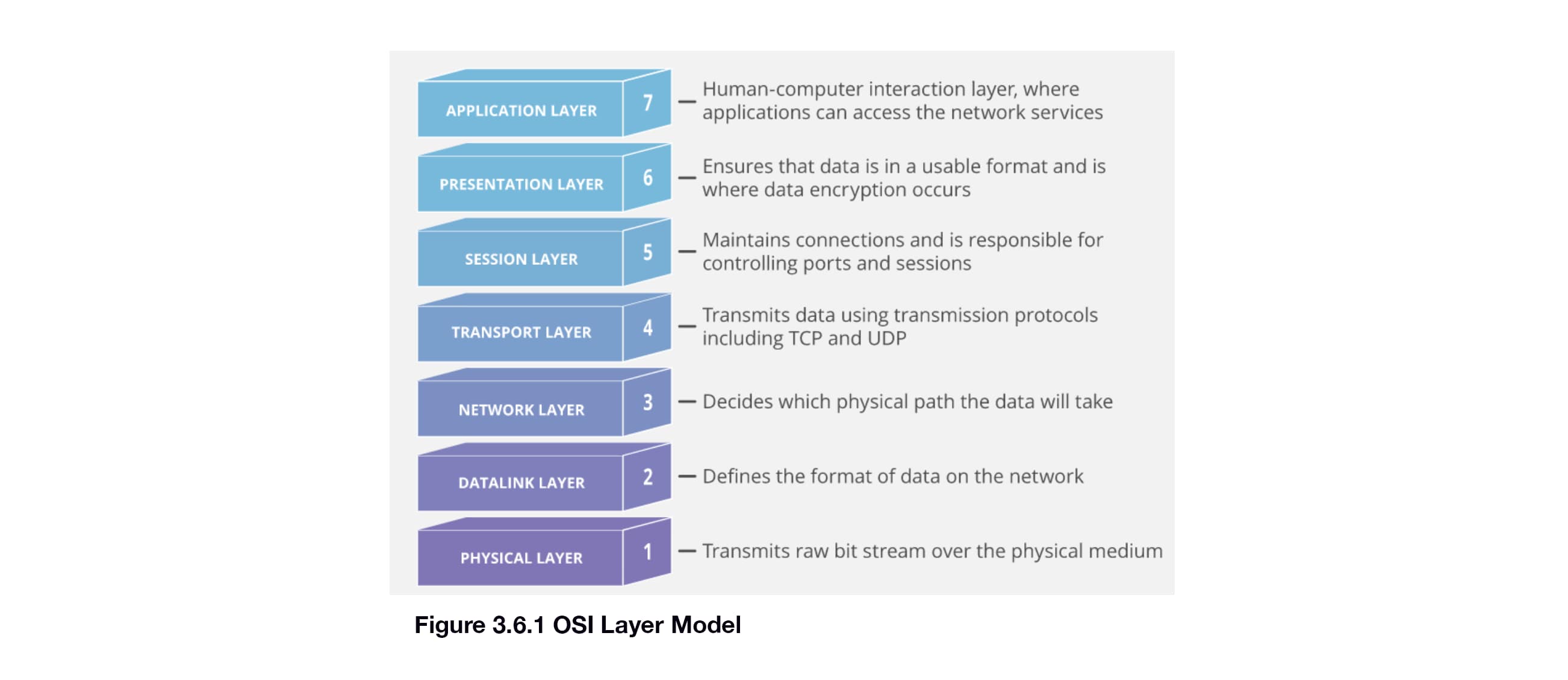
The movement of data through the IIoT solution requires the use of protocols. These protocols need to be well-defined, secure, and, ideally, industry standard. Protocol specifications can include any or all of the following: physical characteristics of connectors and cabling, how to establish a communication channel, the format of the data sent across that channel. The OSI model (Figure 3.6.1 below) delineates the protocol as a set of layers, with each layer having a specific function.
3.6.2 Northbound: Gateway to/from Cloud
There are several standard protocols available for the interface between the gateway and the cloud. A few common ones are defined below, along with a summary diagram.
Hypertext Transfer Protocol (HTTPS) is the protocol of the worldwide web, meant for request/response interactions. The “S” in “HTTPS” stands for “Secure”. HTTP is text-based and therefore fairly verbose, but easy to implement.
Advanced Message Queueing Protocol (AMQP) is a connection oriented, bidirectional, multiplexing message transfer protocol with inherent, compact data encoding. Unlike older protocols such as HTTP, AMQP was designed for IIoT-type connections to the cloud.
MQ Telemetry Transport (MQTT). MQTT is a lightweight client-server transfer protocol for messages. MQTT is useful for IIoT devices due to its compact code space and small message frame sizes.
Constrained Application Protocol (CoAP). The Constrained Application Protocol is a datagram based protocol that can be implemented over a transport layaer such as UDP. CoAP can be thought of a compact version of HTTP that was built for IIoT needs.

3.6.3 Southbound: Gateway to/from Sensors
Similar to the northbound protocols, there are many options for the southbound connection between the gateway and the sensor(s) as well. These options include the northbound protocols listed earlier. However, due to the constraints of the devices and on-premise constraints such as previously deployed production systems and networks, tend to be home-grown or a defacto standard established by a single vendor for its products. Examples include: Zigbee, Bluetooth, WiFi, USB, SimpliciTI. These protocols cover different areas of the OSI stack. As an example Zigbee specifies the Network Layer and above, while WiFi only specifies the Datalink and Physical layers. This separation of functionality enables some mixing and matching of protocols as well.
4.0 Selection Guide
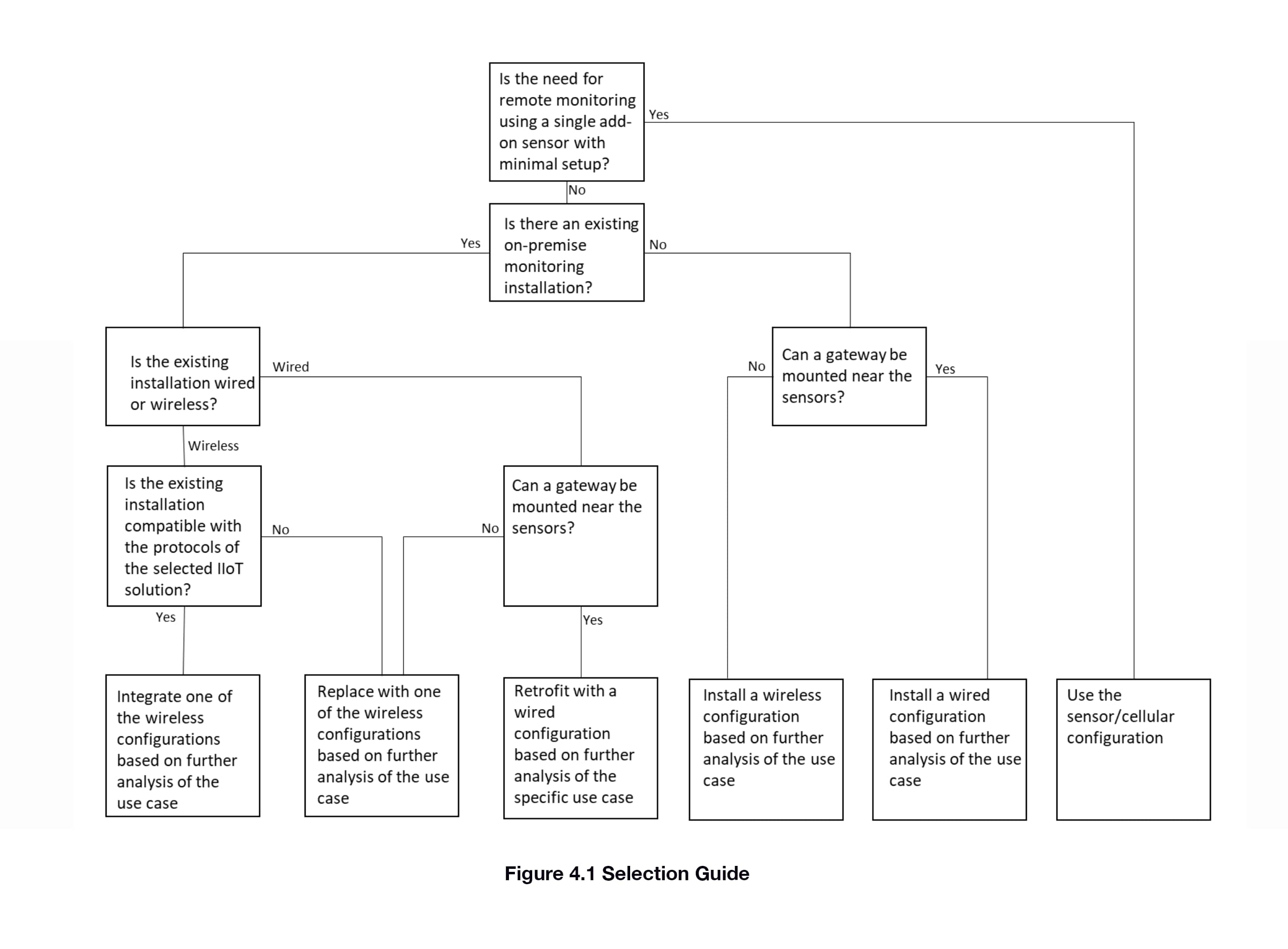
The selection guide (Figure 4.1) provides guidance on choosing between the various configurations in the Design Architecture. The emphasis is on selecting between cellular, wireless, or wired. Determining which wireless configuration or between digital and/or analog wired connections is dependent on further analysis of the specific application.
5.0 The Omega Link IIoT Ecosystem
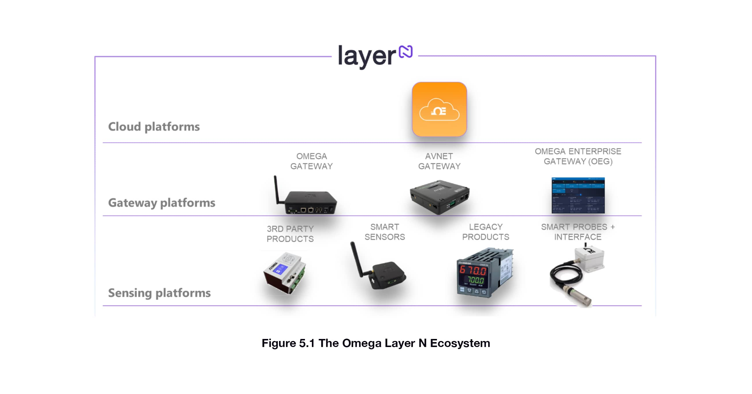
The Omega Link IIoT Ecosystem is an instantiation of the IIoT Design Architecuture as shown below. As expected, there are three layers: cloud, connectivity (via gateways), and sensors. There are multiple options for gateways, both hardware (from Omega and Avnet) and software (the OEG). Sensors come in multiple form factors with both wired and wireless connections. Secure standard protocols are used, including authentication and authorization between layers and devices. The protocols leverage AMQP and SimpliciTI to enable plug and play setup with ecosystem-compatible products.
6.0 References
Microsoft Azure IoT Reference Architecture, Version 2.1, 9/26/2018.
http://www.steves-internet-guide.com/internet-protocol-suite-explained/
http://www.steves-internet-guide.com/iot-messaging-protocols/
https://www.postscapes.com/internet-of-things-protocols/
Appendix A. IIoT Security
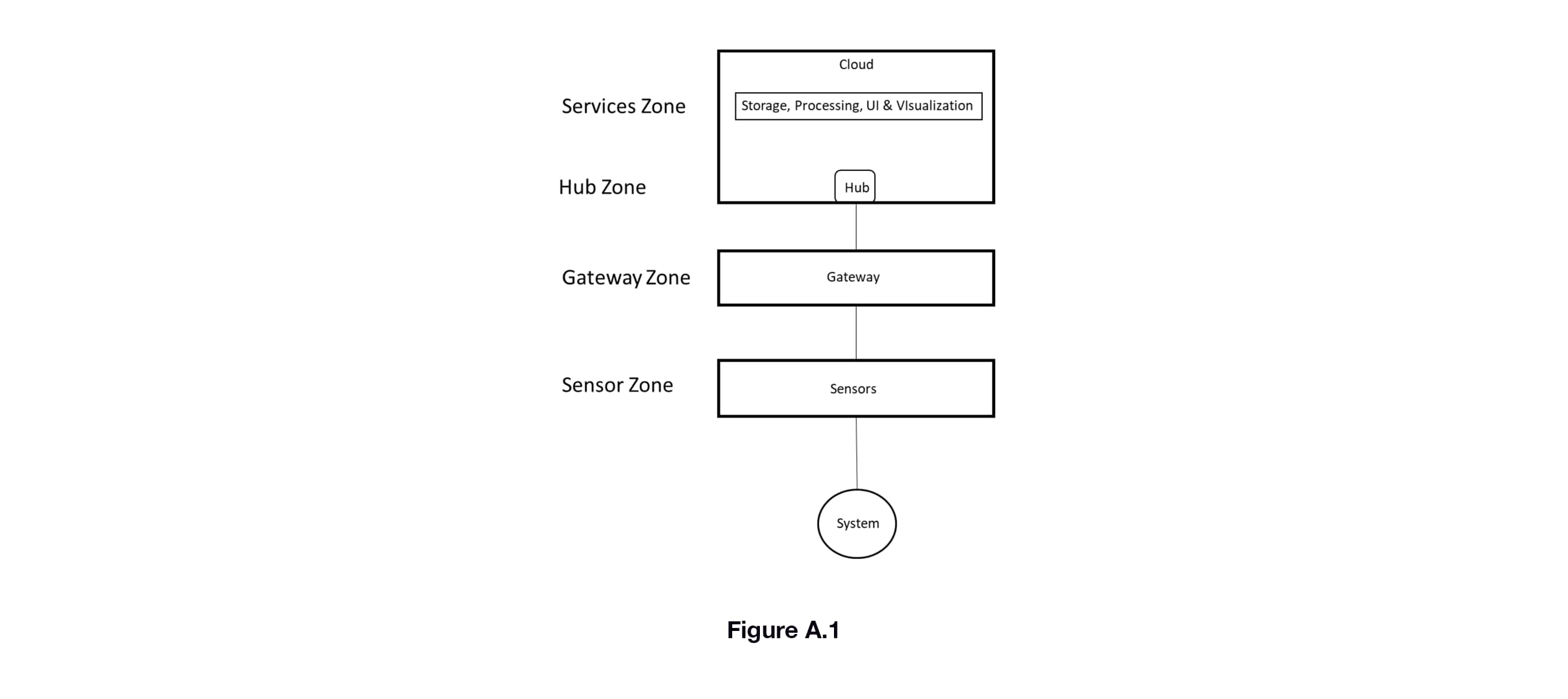
IIoT solutions must be trusted to provide data and information with integrity, as they are monitoring and measuring critical systems and environments. That trust is verified by ensuring the system is secure against threats. Threat modeling is the best approach to designing for security. Using a typical IIoT solution configuration, we can identify several zones (Figure A.1). The boundaries of these zones are where data and information transition from one solution element to another. Threats will be against the boundaries of these zones. To do the threat analysis we can use the STRIDE model, which defines threats as falling into the following categories in the table below.

A detailed explanation of using the STRIDE model is out of the scope of this guide, however, security of an IIoT solution should be validated using this method or its equivalent against each of the zones in Figure A.1.
