Three primary types of temperature probes are commonly used to measure temperature in applications. These are thermocouples, thermistors, and RTDs. All types work by creating or altering an electrical signal in a circuit containing the sensor. Beyond that, there are significant differences between them.
If you encounter a temperature measurement device in the field, which type of sensor it relies on may not be readily apparent. This article will outline the key characteristics of each sensor type, and explain a simple test you can perform to determine whether a temperature sensor is an RTD, a thermocouple, or a thermistor.
How to identify a thermocouple?
Thermocouples are the easiest temperature sensor to identify. A thermocouple probe has two wires identified by a colour code.
- Thermocouples usually come in a 2-wire construction. Sometimes they employ a 3-wire construction if a ground or shielding wire is present.
- They have very low resistance (compared to RTDs and thermistors.)
- Depending on the thermocouple’s type, a thermocouple’s wires may be magnetic.
- Thermocouple wires and extension wires are color coded. The wire colors indicate the thermocouple type.
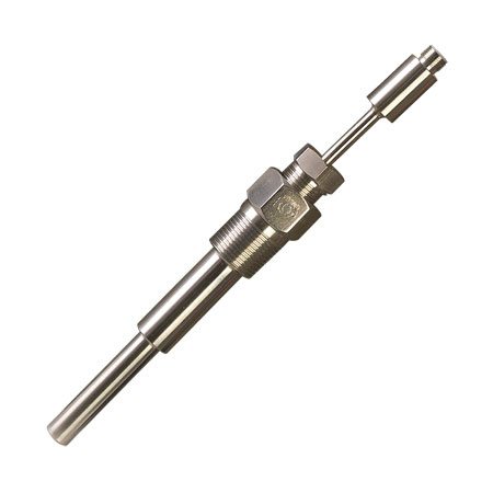
 PR-21SL RTD
See the complete thermocouple colour code standard.
Identifying thermistors and RTDs
Thermistors and RTDs feature either two, three or four wires that are red and white, or red and black. The red wire is the excitation, while the black or white is the ground.To determine whether the sensor is a thermistor or RTD, as well as the type, you must measure the resistance between the two different-coloured wires:
- An RTD PT100 will have a resistance of 100 ohms at 0 °C
- An RTD PT1000 will have a resistance of 1,000 ohms at 0 °C.
Examples
Test case #1:
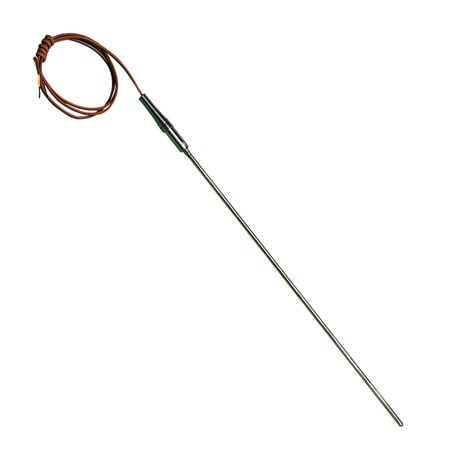
In this example, we have a metallic sheath probe with a long insulated cable and a 2-wire construction. One wire is colored with red insulation. Another wire is colored with yellow insulation. According to the thermocouple color code chart, a K type thermocouple has a wire with red insulation and a wire with yellow insulation. It seems like this might be a thermocouple, but let’s look for more evidence.To determine the sensor’s resistance, use a multimeter set to ohms. A thermocouple should exhibit very low resistance. Attach the negative lead to the red wire, and the positive lead to the yellow. In this case, the reading will be about three ohms. Thus we can conclude that this sensor is a thermocouple.
Test case #2:
This sensor of unknown type has a metal sheath, a cable, and a 2-wire construction. One wire has black insulation and the other has red, which doesn’t match any of the color combinations on the thermocouple chart.Using a multimeter set to ohms, we find that the sensor’s resistance measures 3.023 kiloohms. Because RTDs and thermocouples don't have resistance nearly as high as this, the sensor must be a thermistor.
Test case #3:
For the third example, the sensor is encased in a probe with a metallic sheath, no transition joint, and a cable at its end. It has a 3-wire construction.When the ohm meter’s positive lead is connected to the red lead on the sensor’s wiring, and the negative lead is connected to the white lead on the sensor, we obtain a reading of about 110 ohms. This sensor is probably an RTD because a thermistor or thermocouple wouldn’t have a resistance this low.
To confirm that the sensor is an RTD, we can move the negative lead over to the other wire on the sensor. We should obtain a reading of—or very close to—zero ohms of resistance if the sensor is indeed an RTD. In fact, we get 0.6 ohms, which is a fairly close approximation of zero.
You can repeat this procedure whenever you need to identify a temperature sensor.
If you have additional questions how to use thermocouples, thermistors, or RTDs in your applications, contact us today. A member of our team will be happy to help.


