A Venturi flow meter is a type of differential pressure flow meter that generates a flow measurement by measuring the pressure difference at two different locations in a pipe. This pressure difference is created by constricting the diameter of the pipe, which causes an increase in flow velocity and a corresponding pressure drop. It is through these changes in the fluid flow that the flow rate can be deduced.
Venturi flow meters, like all other types of differential pressure flow meters, function on the principles of the Bernoulli equation, which states that as the speed of the flow of a fluid increases, pressure loss occurs.
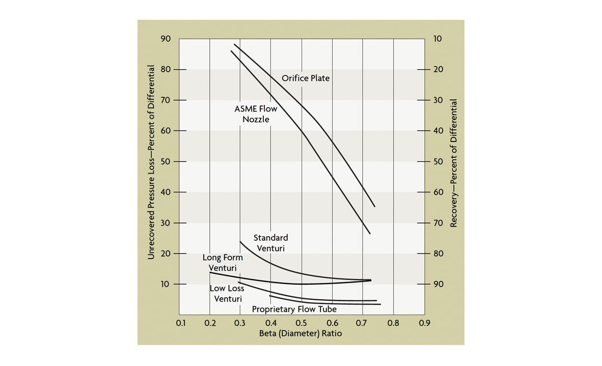
Venturi tubes are available in sizes up to 72” and can pass 25 to 50% more flow than an orifice with the same pressure drop. Furthermore, the total unrecovered head loss rarely exceeds 10% of measured d/p (Figure 1). The initial cost of venturi tubes is high, so they are primarily used on larger flows or on more difficult or demanding flow applications. Venturis are insensitive to velocity profile effects and therefore require less straight pipe run than an orifice. Their contoured nature, combined with the self-scouring action of the flow through the tube, makes the device immune to corrosion, erosion, and internal scale build up. In spite of its high initial cost, the total cost of ownership of this type of instrumentation can still be favorable because of savings in installation and operating and maintenance costs.
 Pressure Loss – Venturi vs Orifice
The classical Herschel venturi has a very long flow element characterized by a tapered inlet and a diverging outlet. Inlet pressure is measured at the entrance, and static pressure in the throat section. The pressure taps feed into a common annular chamber, providing an average pressure reading over the entire circumference of the element. The classical venturi is limited in its application to clean, non-corrosive liquids and gases.
In the short form venturi, the entrance angle is increased, and the annular chambers are replaced by pipe taps (Figure 2-A). The short form venturi maintains many of the advantages of the classical venturi, but at a reduced initial cost, shorter length, and reduced weight. Pressure taps are located ¼ to ½ pipe diameter upstream of the inlet cone, and in the middle of the throat section. Piezometer rings can be used with large venturi tubes to compensate for velocity profile distortions. In slurry service, the pipe taps can be purged or replaced with chemical seals, which can eliminate all dead-ended cavities.
 Gradual Flow Elements
There are several propriety flow tube designs which provide even better pressure recovery than the classical venturi. The best known of these proprietary designs is the universal venturi (Figure 2-B). The various flow tube designs vary in their contours, tap locations, generated d/p, and in their unrecovered head loss. They all have short lay lengths, typically varying between 2 and 4 pipe diameters. These proprietary flow tubes usually cost less than the classical and short-form venturis because of their short lay length. However, they may also require more straight pipe run to condition their flow velocity profiles.
Flow tube performance is much affected by calibration. The inaccuracy of the discharge coefficient in a universal venturi, at Reynolds numbers exceeding 75,000, is 0.5%. The inaccuracy of a classical venturi at Re > 200,000 is between 0.7 and 1.5%. Flow tubes are often supplied with discharge coefficient graphs because the discharge coefficient changes as the Reynolds number drops. The variation in the discharge coefficient of a venturi caused by pipe roughness is less than 1% because there is continuous contact between the fluid and the internal pipe surface.
The high turbulence and the lack of cavities in which material can accumulate make flow tubes well suited for slurry and sludge services. However, maintenance costs can be high if air purging cannot prevent plugging of the pressure taps and lead lines. Plunger-like devices (vent cleaners) can be installed to periodically remove buildup from interior openings, even while the meter is online. Lead lines can also be replaced with button-type seal elements hydraulically coupled to the d/p transmitter using filled capillaries. Overall measurement accuracy can drop if the chemical seal is small, its diaphragm is stiff, or if the capillary system is not temperature-compensated or not shielded from direct sunlight.
Flow Nozzles
The flow nozzle is dimensionally more stable than the orifice plate, particularly in high temperature and high velocity services. It has often been used to measure high flowrates of superheated steam. The flow nozzle, like the venturi, has a greater flow capacity than the orifice plate and requires a lower initial investment than a venturi tube, but also provides less pressure recovery (Figure 1). A major disadvantage of the nozzle is that it is more difficult to replace than the orifice unless it can be removed as part of a spool section.
The ASME pipe tap flow nozzle is predominant in the United States (Figure 2-C). The downstream end of a nozzle is a short tube having the same diameter as the vena contracta of an equivalent orifice plate. The low-beta designs range in diameter ratios from 0.2 to 0.5, while the high beta-ratio designs vary between 0.45 and 0.8. The nozzle should always be centered in the pipe, and the downstream pressure tap should be inside the nozzle exit. The throat taper should always decrease the diameter toward the exit. Flow nozzles are not recommended for slurries or dirty fluids. The most common flow nozzle is the flange type. Taps are commonly located one pipe diameter upstream and ½ pipe diameter downstream from inlet face.
Flow nozzle accuracy is typically 1% AR, with a potential for 0.25% AR if calibrated. While discharge coefficient data is available for Reynolds numbers as low as 5,000, it is advisable to use flow nozzles only when the Reynolds number exceeds 50,000. Flow nozzles maintain their accuracy for long periods, even in difficult service. Flow nozzles can be a highly accurate way to measure gas flows. When the gas velocity reaches the speed of sound in the throat, the velocity cannot increase any more (even if downstream pressure is reduced), and a choked flow condition is reached. Such “critical flow nozzles” are very accurate and often are used in flow laboratories as standards for calibrating other gas flow metering devices.
Nozzles can be installed in any position, although horizontal orientation is preferred. Vertical downflow is preferred for wet stream, gasses, or liquids containing solids. The straight pipe run requirements are similar to those of orifice plates.
Segmental Wedge Elements
The segmental wedge element (Figure 3-A) is a proprietary device designed for use in slurry, corrosive, erosive, viscous, or high-temperature applications. It is relatively expensive and is used mostly on difficult fluids, where the dramatic savings in maintenance can justify the initial cost. The unique flow restriction is designed to last the life of the installation without deterioration.
 Proprietary Elements for Difficult Fluids
Wedge elements are used with 3-in diameter chemical seals, eliminating both the lead lines and any dead-ended cavities. The seals attach to the meter body immediately upstream and downstream of the restriction. They rarely require cleaning, even in services like dewatered sludge, black liquor, coal slurry, fly ash slurry, taconite, and crude oil. The minimum Reynolds number is only 500, and the meter requires only five diameters of upstream straight pipe run.
The segmental wedge has a V-shaped restriction characterized by the H/D ratio, where H is the height of the opening below the restriction and D is the diameter. The H/D ratio can be varied to match the flow range and to produce the desired d/p. The oncoming flow creates a sweeping action through the meter. This provides a scouring effect on both faces of the restriction, helping to keep it clean and free of buildup. Segmental wedges can measure flow in both directions, but the d/p transmitter must be calibrated for a split range, or the flow element must be provided with two sets of connections for two d/p transmitters (one for forward and one for reverse flow).
An uncalibrated wedge element can be expected to have 2% to 5% AR inaccuracy over a 3:1 range. A calibrated wedge element can reduce that to 0.5% AR if the fluid density is constant. If slurry density is variable and/or unmeasured, error rises.
Venturi-Cone Element
The venturi-cone (V-cone) element (Figure 3-B) is another proprietary design that promises consistent performance at low Reynolds numbers and is insensitive to velocity profile distortion or swirl effects. Again, however, it is relatively expensive. The V-cone restriction has a unique geometry that minimizes accuracy degradation due to wear, making it a good choice for high velocity flows and erosive/corrosive applications.
The V-cone creates a controlled turbulence region that flattens the incoming irregular velocity profile and induces a stable differential pressure that is sensed by a downstream tap. The beta ratio of a V-cone is so defined that an orifice and a V-cone with equal beta ratios will have equal opening areas.

Where d is the cone diameter and D is the inside diameter of the pipe.
With this design, the beta ratio can exceed 0.75. For example, a 3-in meter with a beta ratio of 0.3 can have a 0 to 75 gpm range. Published tests results on liquid and gas flows place the system accuracy between 0.25 and 1.2% AR.


