PD flow meters are most widely used as household water meters and millions of such units are produced annually. In industrial and petrochemical applications, positive displacement meters are commonly used for batch charging of both liquids and gases.
How Does a Positive Displacement Flow Meter Work?
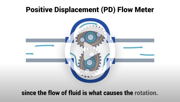
All positive displacement flow meters operate by passing isolated, known volumes of a fluid through a series of gears or chambers within the meter. By counting the number of passed isolated volumes, a flow measurement is obtained. Each positive displacement design uses a different means of isolating and counting these volumes. The frequency of the resulting pulse train is a measure of flow rate, while the total number of pulses gives the size of the batch. While PD meters are operated by the kinetic energy of the flowing fluid, metering pumps determine the flow rate while also adding kinetic energy to the fluid.
PD meters are available in sizes from 1/4" to 12" and can operate with turndowns as high as 100:1, although ranges of 15:1 or lower are much more common. Slippage between the flow meter components is reduced and metering accuracy is therefore increased as the viscosity of the process fluid increases.
The process fluid must be clean and free from contaminants.Particles greater than 100 microns in size must be removed by filtering. PD meters operate with small clearances between their precision-machined parts; wear rapidly destroys their accuracy. For this reason, PD meters are generally not recommended for measuring slurries or abrasive/corrosive fluids. In clean fluid services, however, their precision and wide rangeability make them ideal for custody transfer and batch charging.
Although slippage through the PD meter decreases (that is, accuracy increases) as fluid viscosity increases, pressure drop through the meter also rises. Consequently, the maximum (and minimum) flow capacity of the flow meter is decreased as viscosity increases. The higher the viscosity, the less slippage and the lower the measurable flow rate becomes. As viscosity decreases, the low flow performance of the meter deteriorates. The maximum allowable pressure drop across the meter constrains the maximum operating flow in high viscosity services.
Testing, Calibration, and Provers
All meters with moving parts require periodic testing, recalibration, and repair because wear increases the clearances. Recalibration can be done either in a laboratory or online using a prover.
Gas systems are recalibrated against a bell-jar prover – a calibrated cylindrical bell, liquid sealed in a tank. As the bell is lowered, it discharges a known volume of gas through the meter being tested. The volumetric accuracy of bell-jar provers is on the order of 0.1% by volume, and provers are available in discharge volumes of 2, 5, 10 ft3 and larger.
Liquid systems can be calibrated in the laboratory against either a calibrated secondary standard or a gravimetric flow loop. This approach can provide high accuracy (up to ±0.01% or rate) but requires removing the flow meter from service.
In many operations, especially in the petroleum industry, it is difficult or impossible to remove a flow meter from service for calibration. Therefore, field-mounted and in-line provers have been developed. This type of prover consists of a calibrated chamber equipped with a barrier piston (Figure 1). Two detectors are mounted a known distance (and therefore a known volume) apart. As the flow passes through the chamber, the displacer piston is moved downstream. Dividing the volume of the chamber by the time it takes for the displacer to move from one detector to the other gives the calibrated flow rate. This rate is then compared to the reading of the flow meter under test.
 Figure 1: Field-Mounted, In-Line Flow Prover
Provers are repeatable on the order of 0.02%, and can operate at up to 3,000 psig and 165°F/75°C. Their operating flow range is from as ow as 0.001 gpm to as high as 20,000 gpm. Provers are available for bench-top use, for mounting in truck-beds, on trailers, or in-line.
PD Meter Accessories
PD meter accessories include strainers, filters, air/vapor release assemblies, pulsation dampeners, temperature compensations systems, and a variety of valves to permit dribble cut-off in batching systems. Mechanical registers can be equipped with mechanical or electronic ticket-printers for inventory control and point-of-use sales. Batching flow computers are readily available, as are analog and intelligent digital transmitters. Automatic meter reading (AMR) devices permit the remote retrieval of readings by utility personnel.
Benefits of Positive Displacement Flow Meters
There are many benefits that positive displacement flow meters offer – including:
Accuracy: One of the main benefits of using a PD flow meter is the high level of accuracy that they offer, the high precision of internal components means that clearances between sealing faces is kept to a minimum. The smaller these clearances are, relates to how high the accuracy will be. Only fluid that is able to bypass this seal does not get counted, this is known as ‘by-pass’ or ‘slippage’.
Range and Repeatability: Another benefit is the flow meter’s ability to process a huge range of viscosities and it is not uncommon to experience higher levels of accuracy while processing high viscosity fluids, simply dues to the reduction of by-pass. When considering and comparing flow meter accuracy, it is important to be aware of both ‘linearity’’; i.e., the flow meter’s ability to accurately measure over the complete turndown ratio, and ‘repeatability’, the ability to remain accurate over a number of cycles. This is another area where PD flow meters excel, repeatability of 0.02% and 0.5% linearity are standard.
Reliability: If the correct flow meter has been selected for an application it can be expected to perform without error for many years. Frequently meters are sent in for servicing and recalibration that have been in the field for 10 sometimes 20 years continuous use. This reliability is largely due to the fact that this same proven technology has been in use for over 60 years, allowing the major advances to be focused within the fields of tribology and achieving the required precision at a reasonable cost.
Low Maintenance: The level of recommended maintenance is heavily influenced by the application. For example, if a flow meter is processing a fluid that displays lubricating properties i.e. oil, then routine maintenance can virtually be eliminated. If, however, the fluid has very poor lubricating properties then it is best to discuss the maintenance requirements with your distributor.
It is very uncommon that any maintenance to a PD flow meter would be more frequent than that of other equipment within the same system and can be scheduled to be carried out at the same time, minimalizing downtime.
Limitations of PD Flow Meters
While PD flow meters are very robust, there are limitations to their usage. Firstly, they should not be used for fluids that contain large particles, unless these can be filtered out prior to the fluid entering the measuring chamber. They are also not suitable for applications where large pockets of air are present within the fluid; however, air eliminators are available for these applications.
Another factor that requires consideration is the pressure drop caused by the PD flow meter; although these are minimal, they should also be allowed for in system calculations. As mentioned above when processing fluids with poor lubricating properties, it is recommended that advice is sought from your distributor; various material options are available for these applications.
Types of Positive Displacement Flow Meters
Operation of positive displacement (PD) flow meters consists of separating liquids into accurately measured increments and moving them on. Each segment is counted by a connecting register. Because every increment represents a discrete volume, positive displacement units are popular for automatic batching and accounting applications. Positive displacement flow meters are good candidates for measuring the flows of viscous liquids or for use where a simple mechanical meter system is needed.
Liquid Positive Displacement Flow Meters or Nutating Disk Meters
Nutating disc meters are the most common PD meters. They are used as residential water meters around the world. As water flows through the metering chamber, it causes a disc to wobble (nutate), turning a spindle, which rotates a magnet. This magnet is coupled to a mechanical register or a pulse transmitter. Because the flow meter entraps a fixed quantity of fluid each time the spindle is rotated, the rate of flow is proportional to the rotational velocity of the spindle (Figure 2-A).
 Figure 2: Positive Displacement Flow Meter Designs
Because it must be nonmagnetic, the meter housing is usually made of bronze but can be made from plastic for corrosion resistance or cost savings. The wetted parts such as the disc and spindle are usually bronze, rubber, aluminum, neoprene, Buna-N, or a fluoroelastomer such as FKM. Nutating disc meters are designed for water service and the materials of which they are made must be checked for compatibility with other fluids. Meters with rubber discs give better accuracy than metal discs due to the better sealing they provide.
Nutating disc meters are available in 5/8-in to 2-in sizes. They are suited for 150-psig operating pressures with overpressure to a maximum of 300 psig. Cold water service units are temperature-limited to 120°F. Hot water units are available up to 250°F.
These meters must meet American Water Works Association (AWWA) standards for accuracy. The accuracy of these meters is required to be ±2% of actual flow rate. Higher viscosity can produce higher accuracy, while lower viscosity and wear over time will reduce accuracy. The AWWA requires that residential water meters be re-calibrated every 10 years. Because of the intermittent use patterns of residential users, this corresponds to recalibrating 5/8 x 3/4 in residential water meters after they have metered 5 million gallons. In industrial applications, however, these meters are likely to pass this threshold much sooner. The maximum continuous flow of a nutating disc meter is usually about 60-80% of the maximum flow in intermittent service.
Rotating vane meters (Figure 2-B) have spring-loaded vanes that entrap increments of liquid between the eccentrically mounted rotor and the casing. The rotation of the vanes moves the flow increment from inlet to outlet and discharge. Accuracy of ±0.1% of actual rate (AR) is normal, and larger size meters on higher viscosity services can achieve accuracy to within 0.05% of rate.
Rotating vane meters are regularly used in the petroleum industry and are capable of metering solids-laden crude oils at flow rates as high as 17,500 gpm. Pressure and temperature limits depend on the materials of construction and can be as high as 350°F and 1,000 psig. Viscosity limits are 1 to 25,000 centipoise.
In the rotary displacement meter, a fluted central rotor operates in constant relationship with two wiper rotors in a six-phase cycle. Its applications and features are similar to those of the rotary vane meter.
Oscillating Piston Flow Meters
Oscillating piston flow meters typically are used in viscous fluid services such as oil metering on engine test stands where turndown is not critical (Figure 3). These meters also can be used on residential water service and can pass limited quantities of dirt, such as pipe scale and fine (viz,-200 mesh or -74 micron) sand, but not large particle size or abrasive solids.
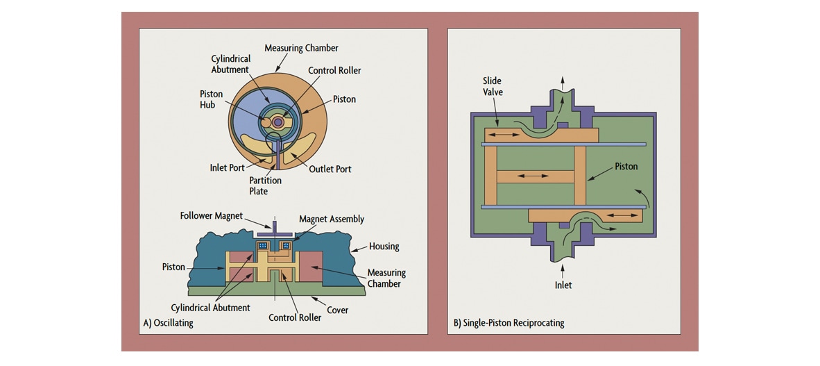 Figure 3: Piston Meter Designs
The measurement chamber is cylindrical with a partition plate separating its inlet port from its outlet. The piston is also cylindrical and is punctured by numerous openings to allow free flow on both sides of the piston and the post (Figure 2-A). The piston is guided by a control roller within the measuring chamber, and the motion of the piston is transferred to a follower magnet which is external to the flowstream. The follower magnet can be used to drive either a transmitter, a register, or both. The motion of the piston is oscillatory (not rotary) since it is constrained to move in one plane. The rate of flow is proportional to the rate of oscillation of the piston.
The internals of this flow meter can be removed without disconnection of the meter from the pipeline. Because of the close tolerances required to seal the piston and to reduce slippage, these meters require regular maintenance. Oscillating piston flow meters are available in 1/2-in to 3-in sizes and can generally be used between 100 and 150 psig. Some industrial versions are rated to 1,500 psig. They can meter flow rates from 1 gpm to 65 gpm in continuous service with intermittent excursions to 100 gpm. Meters are sized so that pressure drop is below 35 psid at maximum flow rate. Accuracy ranges from ±0.5 % AR for viscous fluids to ±2% AR for non-viscous applications. Upper limit on viscosity is 10,000 centipoise.
Reciprocating piston meters are probably the oldest PD meter designs. They are available with multiple pistons, double-acting pistons, or rotary pistons. As in a reciprocating piston engine, fluid is drawn into one piston chamber as it is discharged from the opposed piston in the meter. Typically, either a crankshaft or a horizontal slide is used to control the opening and closing of the proper orifices in the meter. These meters are usually smaller (available in sizes down to 1/10-in diameter) and are used for measuring very low flows of viscous liquids.
Oval Gear and Lobe Meters
The oval gear PD meter uses two fine-toothed gears, one mounted horizontally, the other vertically, with gears meshing at the tip of the vertical gear and the center of the horizontal gear (Figure 4-A). The two rotors rotate opposite to each other, creating an entrapment in the crescent-shaped gap between the housing and the gear. These meters can be very accurate if slippage between the housing and the gears is kept small. If the process fluid viscosity is greater than 10 centipoise and the flowrate is above 20% of rated capacity, accuracy of 0.1% AR can be obtained. At lower flows and at lower viscosity, slippage increases, and accuracy decreases to 0.5% AR or less.
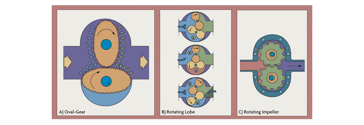 Figure 4: Rotating Positive Displacement Meters
The lubricating characteristics of the process fluid also affect the turndown of an oval gear meter. With liquids that do not lubricate well, maximum rotor speed must be derated to limit wear. Another way to limit wear is to keep the pressure drop across the meter below 15 psid. Therefore, the pressure drop across the meter limits the allowable maximum flow in high viscosity service.
Rotating lobe and impeller type PD meters are variations of the oval gear flow meter that do not share its precise gearing. In the rotating lobe design, two impellers rotate in opposite directions within the ovoid housing (Figure 4-B). As they rotate, a fixed volume of liquid is entrapped and then transported toward the outlet. Because the lobe gears remain in a fixed relative position, it is only necessary to measure the rotational velocity of one of them. The impeller is either geared to a register or is magnetically coupled to a transmitter. Lobe meters can be furnished in 2-in to 24-in line sizes. Flow capacity is 8-10 gpm to 18,000 gpm in the larger sizes. They provide good repeatability (better than 0.015% AR) at high flows and can be used at high operating pressures (to 1,200 psig) and temperatures (to 400°F).
The lobe gear meter is available in a wide range of materials of construction, from thermoplastics to highly corrosion-resistant metals. Disadvantages of this design include a loss of accuracy at low flows. Also, the maximum flow through this meter is less than for the same size oscillatory piston or nutating disc meter.
In the rotating impeller meter, very coarse gears entrap the fluid and pass a fixed volume of fluid with each rotation (Figure 4-C). These meters are accurate to 0.5% of rate if the viscosity of the process fluid is both high and constant, or varies only within a narrow band. These meters can be made out of a variety of metals, including stainless steel, and corrosion-resistant plastics such as PVDF (Kynar). These meters are used to meter paints and, because they are available in 3A or sanitary designs, also milk, juices, and chocolate.
In these units, the passage of magnets embedded in the lobes of the rotating impellers is sensed by proximity switches (usually Hall-effect detectors) mounted external to the flow chamber. The sensor transmits a pulse train to a counter or flow controller. These meters are available in 1/10-in to 6-in sizes and can handle pressures to 3,000 psig and temperatures to 400°F.
Helix Meters
The helix meter is a positive displacement device that uses two radially pitched helical gears to continuously entrap the process fluid as it flows. The flow forces the helical gears to rotate in the plane of the pipeline. Optical or magnetic sensors are used to encode a pulse train proportional to the rotational speed of the helical gears. The forces required to make the helices rotate are relatively small and therefore, in comparison to other PD meters, the pressure drop is relatively low. The best attainable accuracy is about ±0.2% or rate.
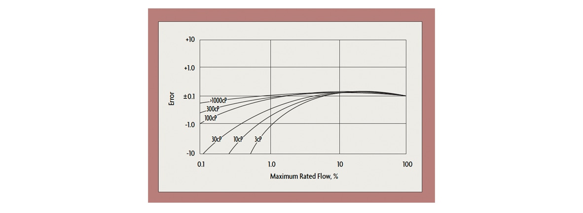 Figure 5: Effect of Viscosity on Low-Flow Accuracy
As shown in Figure 5, measurement error rises as either the operating flowrate or the viscosity of the process fluid drops. Helical gear meters can measure the flow of highly viscous fluids (from 3 to 300,000 cP), making them ideal for extremely thick fluids such as glues and very viscous polymers. Because at maximum flow the pressure drop through the meter should not exceed 30 psid, the maximum rated flow through the meter is reduced as the fluid viscosity increases. If the process fluid has good lubricating characteristics, the meter turndown can be as high as 100:1, but lower (10:1) turndowns are more typical.
Metering Pumps
Metering pumps are PD meters that also impart kinetic energy to the process fluid. There are three basic designs: peristaltic, piston, and diaphragm.
Peristaltic pumps operate by having fingers or a cam systematically squeeze a plastic tubing against the housing, which also serves to position the tubing. This type of metering pump is used in laboratories, in a variety of medical applications, in the majority of environmental sampling systems, and also in dispensing hypochlorite solutions. The tubing can be silicone-rubber or, if a more corrosion-resistant material is desired, PTFE tubing.
Piston pumps deliver a fixed volume of liquid with each "out" stroke and a fixed volume enters the chamber on each "in" stroke (Figure 6-A). Check valves keep the fluid flow from reversing. As with all positive displacement pumps, piston pumps generate a pulsating flow. To minimize the pulsation, multiple pistons or pulsation-dampening reservoirs are installed. Because of the close tolerances of the piston and cylinder sleeve, a flushing mechanism must be provided in abrasive applications. Piston pumps are sized on the basis of the displacement of the piston and the required flow rate and discharge pressure. Check valves (or, on critical applications, double check valves) are selected to protect against backflow.
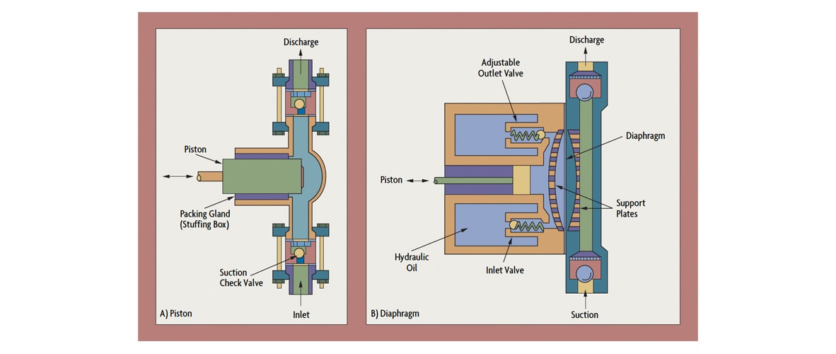 Figure 6: Metering Pump Designs
Diaphragm pumps are the most common industrial PD pumps (Figure 6-B). A typical configuration consists of a single diaphragm, a chamber, and suction and discharge check valves to prevent backflow. The piston can either be directly coupled to the diaphragm or can force a hydraulic oil to drive the diaphragm. Maximum output pressure is about 125 psig. Variations include bellows-type diaphragms, hydraulically actuated double diaphragms, and air-operated, reciprocating double-diaphragms.
Gas Positive Displacement Flow Meters
PD gas meters operate by counting the number of entrapped volumes of gas passed, similar to the way PD meters operate on liquids. The primary difference is that gases are compressible.
Diaphragm gas meters most often are used to measure the flow of natural gas, especially in metering consumption by households. The meter is constructed from aluminum castings with cloth-backed rubber diaphragms. The meter consists of four chambers: the two diaphragm chambers on the inlet and outlet sides and the inlet and outlet chambers of the meter body. The passage of gas through the meter creates a differential pressure between the two diaphragm chambers by compressing the one on the inlet side and expanding the one on the outlet side. This action alternately empties and fills the four chambers. The slide valves at the top of the meter alternate the roles of the chambers and synchronize the action of the diaphragms, as well as operating the crank mechanism for the meter register.
Diaphragm meters generally are calibrated for natural gas, which has a specific gravity of 0.6 (relative to air). Therefore, it is necessary to re-calibrate the flow rating of the meter when it is used to meter other gases. The calibration for the new flow rating (QN) is obtained by multiplying the meter's flow rating for natural gas (QC) by the square root of the ratio of the specific gravities of natural gas (0.6) and the new gas (SGN):
Qn=Qc(0.6/SGn)1.5
Diaphragm meters are usually rated in units of cubic feet per hour and sized for a pressure drop of 0.5-2 in H2O. Accuracy is roughly ±1% of reading over a 200:1 range. They maintain their accuracy for long periods of time, which makes them good choices for retail revenue metering applications. Unless the gas is unusually dirty (producer gas, or recycled methane from composting or digesting, for example), the diaphragm meter will operate with little or no maintenance indefinitely.
Lobe gear meters (or lobed impeller meters, as they are also known), also are used for gas service. Accuracy in gas service is ±1% of rate over a 10:1 turndown, and typical pressure drop is 0.1 psid. Because of the close tolerances, upstream filtration is required for dirty lines.
Rotating vane meters measure the flow of gas in the same ranges as do lobe gear meters (up to 100,000 ft3/hr) but can be used over a wider 25:1 turndown. They also incur a lower pressure drop of 0.05 in H2O for similar accuracy, and, because the clearances are somewhat more forgiving, upstream filtration is not as critical.
High-Precision Positive Displacement Systems
High-precision gas meters are usually a hybrid combining a standard positive displacement meter and a motor drive that eliminates the pressure drop across the meter. Equalizing the inlet and outlet pressures eliminates slip flows, leakage, and blow-by. In high-precision gas flow meter installations, high-sensitivity leaves are used to detect the pressure differential, and displacement transducers are used to measure the deflection of the leaves (Figure 7-A). Designed to operate at ambient temperatures and at up to 30 psig pressures, this meter is claimed to provide accuracy to within 0.25% of reading over a 50:1 range and 0.5% over a 100:1 range. Flow capacity ranges from 0.3-1,500 scfm.
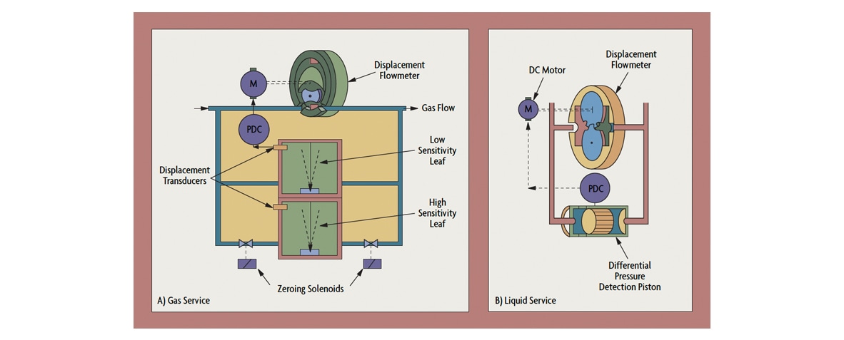 Figure 7: High-Pressure PD Meters Equalize Inlet and Outlet Pressures
For liquid service, a servomotor-driven oval-gear meter equalizes the pressure across the meter. This increases accuracy at low flows and under varying viscosity conditions (Figure 7- B). This flow meter uses a very sensitive piston to detect the meter differential and drives a variable speed servomotor to keep it near zero. This design is claimed to provide 0.25% of rate accuracy over a 50:1 range at operating pressures of up to 150 psig. High precision flow meters are used on engine test stands for fuel flow measurement (gasoline, diesel, alcohol, etc.). Flow ranges from 0.04-40 gph are typical. Vapor separators are usually included, to prevent vapor lock.
