The orifice plate flow meter is a type of differential pressure flow meter that is commonly used in clean liquid, gas, and stream mass flow measurement. It is available for all pipe sizes, and if the pressure loss it requires is free, it is very cost-effective for measuring fluid flows in larger pipes (over 6" diameter). The orifice plate is also approved by many standards organizations for the custody transfer of liquids and gases.
The orifice flow equations – which make use of the Bernoulli Equation – that are used today still differ from one another, although the various standards organizations are working to adopt a single, universally accepted orifice flow equation. Orifice sizing programs usually allow the user to select the flow equation desired from among several.
How Does an Orifice Plate Flow Meter Work?
The orifice plate can be made of any material, although stainless steel is the most common. The thickness of the plate used (1/8 – 1/2") is a function of the line size, the process temperature, the pressure, and the differential pressure. The traditional orifice is a thin circular plate (with a tab for handling and for data), inserted into the pipeline between the two flanges of an orifice union. This method of installation is cost-effective, but it calls for a process shutdown whenever the plate is removed for maintenance or inspection. In contrast, an orifice fitting allows the orifice to be removed from the process without depressurizing the line and shutting down flow. In such fittings, the universal orifice plate, a circular plate with no tab, is used.
The concentric orifice plate (Figure 1 – A) has a sharp (square-edged) concentric bore that provides an almost pure line contact between the plate and the fluid, with negligible friction drag at the boundary. The beta (or diameter) ratios of concentric orifice plates range from 0.25 to 0.75. The maximum velocity and minimum static pressure occurs at some 0.35 to 0.85 pipe diameters downstream from the orifice plate. That point is called the vera contracta. Measuring the differential pressure at a location close to the orifice plate minimizes the effect of pipe roughness, since friction has an effect on the fluid and the pipe wall.
 Figure 1: Orifice Plate Openings
Flange taps are predominantly used in the United States and are located 1 inch from the orifice plate’s surfaces (Figure 2). They are not recommended for use on pipelines under 2 inches in diameter. Corner taps are predominant in Europe for all sizes of pipe and are used in the United States for pipes under 2 inches (Figure 2). With corner taps, the relatively small clearances represent a potential maintenance problem. Vena contracta taps (which are close to the radius taps, Figure 1) are located one pipe diameter upstream from the plate, and downstream at the point of vena contracta. This location varies (with beta ratio and Reynolds number) from 0.35D to 0.8D.
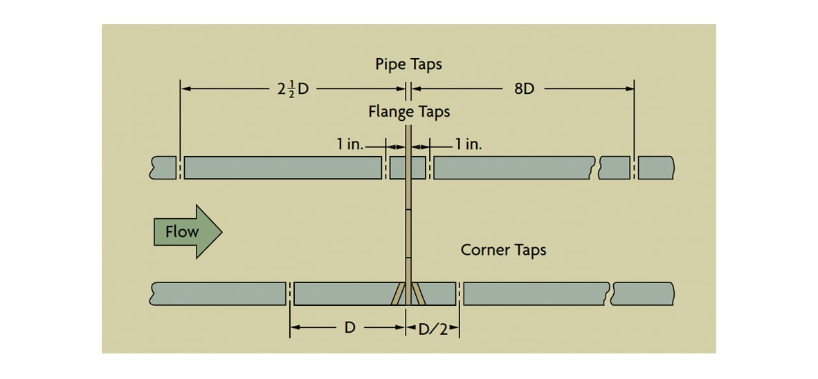 Figure 2: Differential Pressure Tap Location Alternatives
The vena contracta taps provide the maximum pressure differential, but also the most noise. Additionally, if the plate is changed, it may require a change in the tap location. Also, in small pipes, the vena contracta might lie under a flange. Therefore, vena contracta taps normally are used only in pipe sizes exceeding six inches.
Radius taps are similar to vena contracta taps, except the downstream tap is fixed at 0.5D from the orifice plate (Figure 2). Pipe taps are located 2.5 pipe diameters downstream from the orifice (Figure 2). They detect the smallest pressure difference and, because of the tap distance from the orifice, the effects of pipe roughness, dimensional inconsistencies, and, therefore, measurement errors are the greatest.
Orifice Types & Selection
The concentric orifice plate is recommended for clean liquids, gases, and steam flows when Reynolds numbers range from 20,000 to 107 in pipes under six inches. Because the basic orifice flow equations assume that flow velocities are well below sonic, a different theoretical and computational approach is required if sonic velocities are expected. The minimum recommended Reynolds number for flow through an orifice (Figure 3) varies with the beta ratio of the orifice and with the pipe size. In larger size pipes, the minimum Reynolds number also rises. Because of this minimum Reynolds number consideration, square-edged orifices are seldom used on viscous fluids. Quadrant-edged and conical orifice plates (Figure 4) are recommended when the Reynolds number is under 10,000. Flange taps, corner, and radius taps can all be used with quadrant-edged orifices, but only corner taps should be used with a conical orifice.
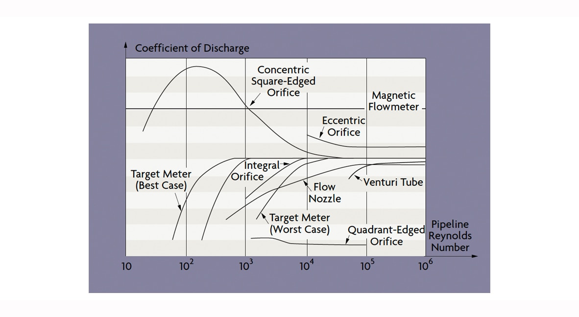 Figure 3: Effect of Reynolds Numbers on Various Flowmeters
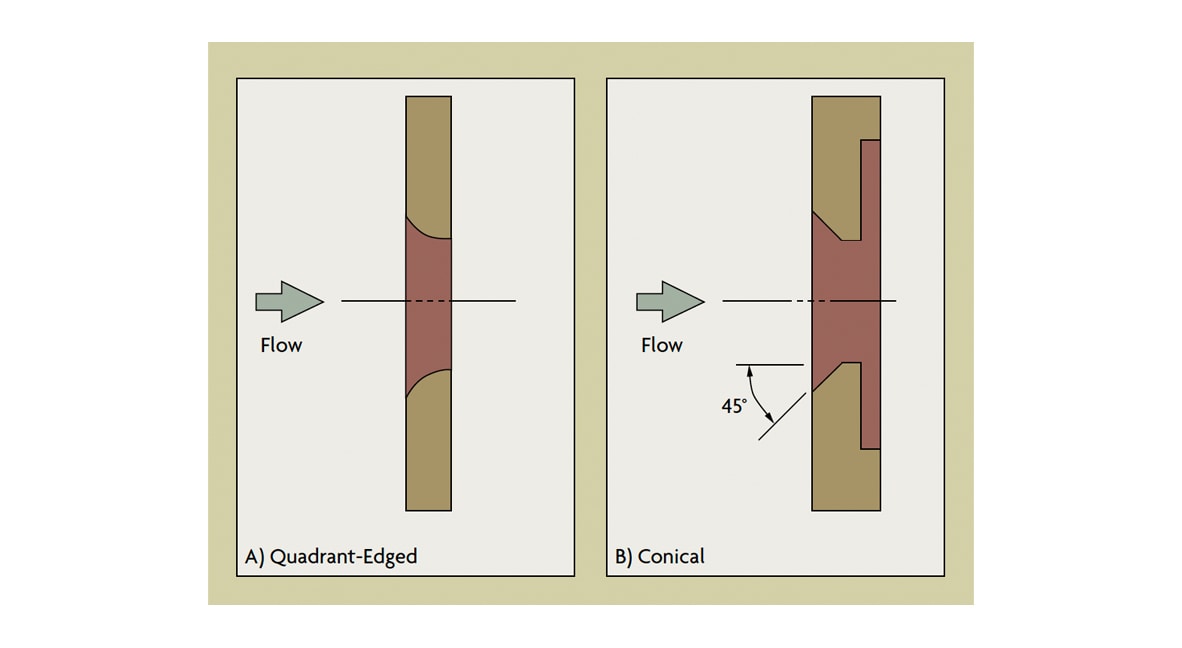 Figure 4: Orifices for Viscous Flows
Concentric orifice plates can be provided with drain holes to prevent buildup of entrained liquids in gas streams, or with vent holes for venting entrained gases from liquids (Figure 1-A). The unmeasured flow passing through the vent or drain hole is usually less than 1% of the total flow if the hole diameter is less than 10% of the orifice bore. The effectiveness of vent/drain holes is limited, however, because they often plug up.
Concentric orifice plates are not recommended for multi-phase fluids in horizontal lines because the secondary phase can build up around the upstream edge of the plate. In extreme cases, this can clog the opening, or it can change the flow pattern, creating measurement error. Eccentric and segmental orifice plates are better suited for such applications. Concentric orifices are still preferred for multiphase flows in vertical lines because accumulation of material is less likely and the sizing data for these plates is more reliable.
The eccentric orifice (Figure 1-B) is similar to the concentric except that the opening is offset from the pipe’s centerline. The opening of the segmental orifice (Figure 1-C) is a segment of a circle. If the secondary phase is a gas, the opening of an eccentric orifice will be located towards the top of the pipe. If the secondary phase is a liquid in a gas or a slurry in a liquid stream, the opening should be at the bottom of the pipe. The drainage area of the segmental orifice is greater than that of the eccentric orifice, and, therefore, it is preferred in applications with high proportions of the secondary phase.
These plates are usually used in pipe sizes exceeding four inches in diameter and must be carefully installed to make sure that no portion of the flange or gasket interferes with the opening. Flange taps are used with both types of plates and are located in the quadrant opposite the opening for the eccentric orifice, in line with the maximum dam height for the segmental orifice.
For the measurement of low flow rates, a d/p cell with an integral orifice may be the best choice. In this design, the total process flow passes through the d/p cell, eliminating the need for lead lines. These are proprietary devices with little published data on their performance; their flow coefficients are based on actual laboratory calibrations. They are recommended for clean, single-phase fluids only because even small amounts of build-up will create significant measurement errors or will clog the unit. Restriction orifices are installed to remove excess pressure and usually operate at sonic velocities with very small beta ratios. The pressure drop across a single restriction orifice should not exceed 500 psid because of plugging or galling. In multi-element restriction orifice installations, the plates are placed approximately one pipe diameter from one another in order to prevent pressure recovery between the plates.
Orifice Performance
Although it is a simple device, the orifice plate is, in principle, a precision instrument. Under ideal conditions, the inaccuracy of an orifice plate can be in the range of 0.75-1.5% AR. Orifice plates are, however, quite sensitive to a variety of error-inducing conditions. Precision in the bore calculations, the quality of the installation, and the condition of the plate itself determine total performance. Installation factors include tap location and condition, condition of the process pipe, adequacy of straight pipe runs, gasket interference, misalignment of pipe and orifice bores, and lead line design. Other adverse conditions include the dulling of the sharp edge or nicks caused by corrosion or erosion, warpage of the plate due to waterhammer and dirt, and grease or secondary phase deposits on either orifice surface. Any of the above conditions can change the orifice discharge coefficient by as much as 10%. In combination, these problems can be even more worrisome and the net effect unpredictable. Therefore, under average operating conditions, a typical orifice installation can be expected to have an overall inaccuracy in the range of 2 to 5% AR.
The typical custody-transfer grade orifice meter is more accurate because it can be calibrated in a testing laboratory and is provided with honed pipe sections, flow straighteners, senior orifice fittings, and temperature-controlled enclosures.

