A mass flow meter is a type of flow meter and is a device that accurately measures the mass flow rate of a fluid moving through a pipe. Mass flow rate measures mass per unit time, differing from volumetric flow rate – which measures volume per unit time.
Mass flow measurement is the basis of most recipe formulations, material balance determinations, billing, and custody transfer operations throughout industry. With these being the most critical flow measurements in a processing plant, the reliability and accuracy of mass flow detection is of the upmost importance.
How Does a Mass Flow Meter Work?
The two flow technologies that are used to measure mass flow are inertial and thermal. Inertia meters, known as Coriolis flow meters, use the Coriolis Effect to measure mass flow rate. When a fluid is flowing in a pipe and it is subjected to Coriolis acceleration through the mechanical introduction of apparent rotation into the pipe, the amount of deflecting force generated by the Coriolis inertial effect will be a function of the mass flow rate of the fluid.
Thermal mass flow meters also measure the mass flow rate of liquids and gases directly and the function on the principles of heat transfer using a heating element and temperature sensors.
Types of Mass Flow Meters
Coriolis Mass Flow Meters
Coriolis mass flow meters introduce an artificial Coriolis acceleration – an apparent force that acts relative to a rotating frame – into the flowing stream and measure mass flowrate by detecting the resulting angular momentum.
When a fluid is flowing in a pipe and it is subjected to Coriolis acceleration through the mechanical introduction of apparent rotation into the pipe, the amount of deflecting force generated by the Coriolis inertial effect will be a function of the mass flow rate of the fluid.
Thermal Mass Flow Meters
Thermal mass flow meters also measure the mass flowrate of gases and liquids directly. These meters operate either by introducing a known amount of heat into the flowing stream and measuring an associated temperature change or by maintaining a probe at a constant temperature and measuring the energy required to do so. The components of a basic thermal mass flow meter include two temperature sensors and an electric heater between them. The heater can protrude into the fluid stream or can be external to the pipe.
Common Mass Flow Meter Applications
Mass flow meters are used frequently in monitoring or controlling mass-related processes (like chemical reactions) that depend on the relative masses of unreacted ingredients, such as recipe formulations, material balance determinations, and billing and custody transfer operations. As these are the most critical flow measurements in a processing plant, the reliability and accuracy of mass flow measurement is very important.
Coriolis mass flow meters are used in many different applications in a wide variety of industries as well as in scientific applications – measuring both corrosive and clean gases and liquids. They provide high accuracy in mass flow measurement density measurement, temperature measurement, and viscosity. Thermal mass flow meters are often used in monitoring or controlling mass-related processes such as chemical reactions that depend on the relative masses of unreacted ingredients.
Some common gas-flow applications for thermal mass flow meters include combustion air measurement in large boilers, semiconductor process gas measurement in the chemical and petrochemical industries, research and development applications, gas chromatography, and filter and leak testing. In detecting the mass flow of compressible vapors and gases, the measurement is unaffected by changes in pressure and/or temperature. One of the capabilities of thermal mass flow meters is to accurately measure low gas flow rates or low gas velocities (under 25 ft. per minute) – much lower than can be detected with any other device. Thermal flow meters provide high rangeability (10:1 to 100:1) if they are operated in constant-temperature-difference mode.
On the other hand, if heat input is constant, the ability to detect very small temperature differences is limited and both precision and rangeability drop off. At normal flows, measurement errors are usually in the 1-2% full scale range.
What Are the Limitations of a Mass Flow Meter?
Mass flow meters can have very high rangeability and high accuracy, but they also have serious limitations. Environmental variables and reading, calculation, and adjustment errors can cause a decrease in efficiency, potential damage to equipment, and, ultimately, a reduction in accuracy.
Potential problems with mass flow meters include:
- Coriolis mass flow meters require high flow velocities for detection – and this results in high pressure drops.
- Coriolis meters are expensive when compared with other flow meters. They are also not available for larger sized pipes.
- Thermal mass flow meters are affected by condensation of moisture (in saturated gases) on the temperature detector – this will cause the thermometer to read low and can lead to corrosion.
- Thermal mass flow meters are affected by coating or material build-up on the sensor – this will inhibit heat transfer and cause the meter to read low.
- Thermal mass flow meters are affected by variations in the specific heat caused by changes in the gas’s composition.
Mass Flow Measurement: A History
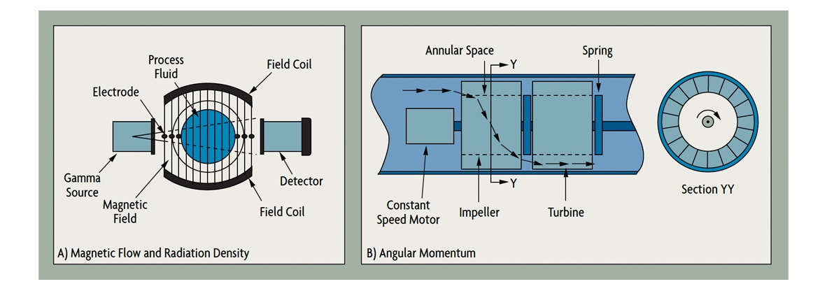
In the past, mass flow was often calculated from the outputs of a volumetric flow meter and a densitometer. Density was either directly measured (Figure 1-A) or was calculated using the outputs of process temperature and pressure transmitters. These measurements were not very accurate because the relationship between process pressure or process temperature and density are not always precisely known – each sensor adds its own separate error to the overall measurement error, and the speed of response of such calculations is usually not sufficient to detect step changes in flow.
 Figure 1: Traditional Mass Flow Meters
One of the early designs of self-contained mass flow meters operated using angular momentum (Figure 1-B). It had a motor-driven impeller that imparted angular momentum (rotary motion) by accelerating the fluid to a constant angular velocity. The higher the density, the more angular momentum was required to obtain this angular velocity. Downstream of the driven impeller, a spring-held stationary turbine was exposed to this angular momentum.
The resulting torque (spring torsion) was an indicatin of mass flow. These meters all had moving parts and complex mechanical designs. First developed for the measurement of aircraft fuel, some are still in use. However, because of their complex nature and high maintenance costs, they are gradually being replaced by more robust and less maintenance-demanding designs.
Mass flow also can be measured by batch weighing or by combining an accurate level sensor with a densitometer. Another method is to mount two d/p transmitters on the lower part of an atmospheric tank at different elevations. In this case, the output of the top d/p cell will vary with the level in the tank, while the lower one will measure the hydrostatic head over a fixed elevational distance. This pressure differential yields the density of the material in the tank. Such systems have been used to measure the total mass flow of slurries.
Mass Flow Versus Volume Flow Measurement
Mass flow measurement and volume flow measurement are both important techniques used to measure the amount of flow in a system. While the two concepts are related, they differ in a few key ways. Mass flow measurement deals with the amount of mass that is moving through a system over a given period of time, typically measured in grams per second.Volume flow measurement is concerned with the amount of space that the mass is occupying over a given time, usually measured in liters per second. One similarity between the two is that they both measure the rate at which something is flowing through a system. Additionally, both measurements are typically used in combination with other measurements to get a better understanding of the system as a whole.


