A Coriolis mass flow meter, which is a type of flow meter that measures mass through inertia and is widely considered to be the most accurate type of flow meter, is used in many industrial applications to measure flow rate. Based on the principles of the Coriolis effect, Coriolis mass flow meters have been in use since the 1970s.
To ensure accurate measurement, it is essential that a Coriolis mass flow meter is properly installed into an industrial processing system.
How to Install Your Coriolis Flow Meter
There are no Reynolds number limitations associated with Coriolis meters. They are also insensitive to velocity profile distortion and swirl. Therefore, there is no requirement for straight runs of relaxation piping upstream or downstream of the meter to condition the flow.
The meter should be installed so that it will remain full of liquid and so air cannot get trapped inside the tubes. In sanitary installations, the meter must also drain completely.
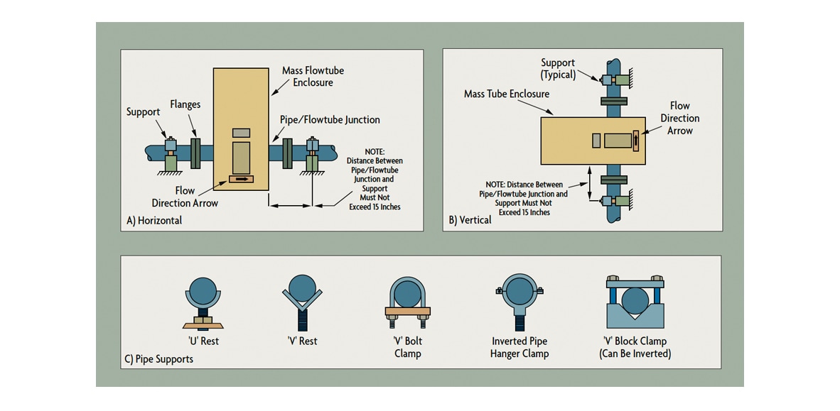
The most desirable installation is in vertical upward flow pipes (Figure 1-B), but installations in horizontal lines (Figure 1-A) are also acceptable. Installations where the flow is downward in a vertical pipe are not recommended.
 Figure 1: Installation Variations of the Coriolis Meter
In newer Coriolis designs, normal pipe vibration should not affect the performance of the Coriolis meter if it is properly supported by the process piping (Figure 1-C). No special supports or pads are needed for the flow tube, but standard piping supports should be located on either side of the meter. If the installation instructions require special hardware or supports, the particular meter design is likely to be sensitive to vibration, and the pulsation dampeners, flexible connectors, and mounting/clamping attachments recommended by the manufacturer should be carefully installed.
If your application requires that you install two Coriolis flow meters in series or mount two Coriolis meters near each other, the manufacturer should be consulted to prevent crosstalk between the two units.
If air bubbles are likely to be present in the process fluid, it is recommended to install an air release upstream of the meter. System design characteristics that result in the presences of air (and which can often be eliminated at the design stage) include:
- Common piping used for pumping into and out of storage tanks
- Allowing the formation of a cortex in stirred vessels under low-level conditions
- Allowing air leakage through packing glands of pumps that develop high vacuums on the suction side (this can occur when pumping from underground storage)
- Vaporization of stagnant process fluid in pipes exposed to the sun
- High valve pressure drops causing vaporization and flashing
- Allowing the pipe to drain for any reason, including lack of check valves
- Allowing storage tanks, trucks, or railroad cars to drain completely
- Using the same pipe for pumping different materials at different times
- Allowing foam formation by high turbulence in high velocity fluids
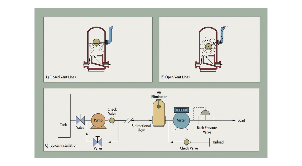
It is recommended to install (upstream of the meter) strainers, filters, or air/vapor eliminators as required to remove all undesirable secondary phases. Figure 2 illustrates an air eliminator installation. Its function is to slow the velocity of the liquid, thereby allowing time for the entrained air to separate and be removed by venting. The rise and fall of the liquid level in the eliminator due to the accumulation of free air closes and opens the vent valve and discharges the air (Figure 2 - A & B).
 Figure 2: Air Releases Installed Upstream from the Meter
Control valves should be installed downstream of the meter to increase the backpressure on the meter and lower the probability of cavitation or flashing.
When the process fluid must be held at a higher temperature, some Coriolis meters can be supplied with steam jackets. As an alternative, electrical heating tape can be added to the housing. Jackets or heating tapes must be installed by the manufacturer.
When flow-metering is not required, a Coriolis meter can be used solely as a densitometer. In that case, to minimize cost, usually a small (1/2 in) meter is installed in a by-pass line. Such a configuration is acceptable only in clean services that will not clog the small bore of the meter. In addition, a restriction must be placed in the main piping (between the by-pass taps) to ensure a flow through the meter.
How to Calibrate Your Coriolis Flow Meter
Prior to zeroing the meter, all air should be removed. This can be accomplished by circulating the process fluid through the meter for several minutes at a velocity of approximately 2-6 ft/sec. On batching or other intermittent flow applications, the meter should stay flooded so that it does not need to be re-purged. All meters should be so installed so they can be zeroed while filled with liquid.
When zeroing the meter, any associated pumps or other equipment should be running so that their noise can be zeroed out. This can be achieved in most cases by locating a shut-off value downstream of the meter and either operating the pump with its discharge blocked, which is acceptable with centrifugal pumps for a short period, or by opening the pump bypass on positive displacement pumps. Valves used in zeroing the meter should provide tight shut-off; double-seated valves are preferred.
Meters that are expected to be calibrated in-line must be provided with block and bypass valves so that the reference standard (master) meter can be installed and disconnected without interrupting the process. The requirements for in-line calibration (for ISO 9000 verification) consist of comparing the output of the meter against a reference standard of higher accuracy, such as a dead-weight calibrated weigh tank.
Before Coriolis meters, the reference standard was expected to be an order of magnitude more accurate than the meter being calibrated; however, due to the high accuracy of Coriolis meters, this is rare.
In less critical installations (where weigh tanks are not used), volumetric provers or master meters (typically another Coriolis or a turbine meter calibrated at a flow laboratory) are used. When a volumetric reference is used in calibrating a mass flow meter, the fluid density must be very precisely determined.


