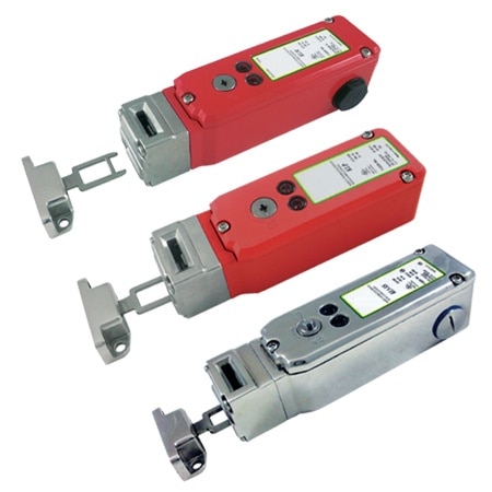
Guard locking switches are designed to provide robust position interlock detection for moving guards and provide a lock mechanism to keep the guard closed until the hazard has been removed. They are tongue operated and are designed to fit to the leading edge of sliding or hinged machine guards to provide positively operated switching contacts and provide a tamper resistant key mechanism that is not easily defeatable.
Depending upon the risk assessment for the application, they can be used independently to provide positively operated contacts to EN60947-5-1 or they can be used in combination with any dual channel safety monitoring relays to provide up to PLe Category 4 to ISO13849-1 or SIL3 EN62061. They are offered with a choice of various actuators to aid installation and maintain durability throughout the rigorous applications of Factory Automation, Packaging, Food Processing, Pharmaceutical and Petro- Chemical Industries.
The switch is rigidly mounted to the frame of the guard or machine. The actuator is fitted to the moving part (frame) of the guard and is aligned to the switch entry aperture. The actuator profile is designed to match a cam mechanism within the switch head and provides a positively operated interlock switch. When the actuator is inserted into the switch the safety contacts can be closed and allow the machine start circuit to be enabled. When the solenoid receives the required signal the safety contacts are positively opened, the machine circuit is broken and the guard door can be opened. They can be used in combination with safety timers to provide a delay before allowing the guard to open (e.g. for machines which require run down). Standard versions automatically spring lock at the insertion of the actuator and will only unlock when power is applied to the solenoid. These switches are sealed to NEMA 6 (IP67) and provide long term protection against moisture ingress.
Specifications Standards: ISO14119, EN60947-5-1, EN60204-1, ISO13849-1, EN62061 UL508 Safety Classification and Reliability Data: Mechanical Reliability B10d: 2.5 x 10⁶ operations at 100 mA load ISO13849-1: Up to PLe depending upon system architecture EN62061: Up to SIL3 depending upon system architecture Safety Data–Annual Usage: 8 cycles per hour/24 hours per day/365 days PFHd: 3.44 x 10⁻⁸ Proof Test Interval (Life): 35 years MTTFd: 356 years Solenoid Voltage: 110 Vac or 24 Vdc/Vac (see To Order table) Solenoid Wattage: 12W LED2 Supply Voltage: 24 Vdc Utilization Category: AC15 A300 3A Thermal Current (lth): 5A Rated Insulation/Withstand Voltages: 600 Vac/2500 Vac Travel for Positive Opening: 10 mm (0.39") Actuator Entry Minimum Radius: Standard: 175 mm (6.89") Heavy-Duty: 100 mm (3.93") Maximum Approach/Withdrawal Speed: 600 mm/s Holding Force: KLP Series: F1Max, 1800N, Fzh 1384N KLM, KL3-SS Series: F1Max, 2000N, Fzh 1538N Body Material: KLM Series: Die cast (painted red) KLP Series: Polyester KL3-SS Series: 316 Stainless Steel Head Material: KLM Series: Die cast (painted red) or 316 stainless steel KLP Series: 316 stainless steel KL3-SS Series: 316 stainless steel Enclosure Protection: KLM, KLP Series: NEMA 6 (IP67) KL3-SS Series: NEMA PW12 (IP67K), NEMA 6 (IP67) Operating Temperature: -25 to 50°C (-13 to 122°F) Vibration: IEC 68-2-6 10 to 55 Hz + 1 Hz; excursion: 0.35 mm 1 octave/min Conduit Entry:1/2 NPT or M23 12-way (see To Order table) Fixing: 4 x M5 Weight (of Switch): KLM Series: 770 g (1.7 lb), 795 g (1.75 lb) with SS head KLP Series: 575 g (1.3 lb) KL3-SS Series: 1290 g (2.85 lb)