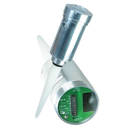
The LVRD500 Series, a logical extension to the ultrasonic sensor series, is designed for applications requiring non-contact liquid level measurement, in which ultrasonic level measurement is not acceptable.
The LVRD500 Series radar technology can be adjusted for variables such as materials to be measured, vessel configuration, and system interface. These sensors are ideal when vapor, dust, or a foaming surface prevents ultrasonic-wave measurements.
LVRD500 Series radar sensors can detect the level under a layer of light dust or airy foam, but if the dust particle size increases, or if the foam or dust gets thick, they will no longer detect the liquid level. Instead, the level of the dust or foam will be measured. Internal piping, deposits on the antenna, multiple reflections, or reflections from the wall can interfere with the proper operation of the radar sensor. Other sources of interference are rat-holing and bridging of solids, as well as angled process material surfaces that can reflect the radar beam away from the receiver.
The sensors use improved microwave-pulse technology to track any target material from the tip of the antenna to the bottom of the tank. Their power, pulse widths, and sensitivity depend on the distance of the target from the antenna and the dielectric constant of the reflecting material.
LVRD500 sensors feature "echo marker" signal processing, making them among the most technologically advanced pulse radar systems on the market.
This technology provides reliable, continuous pulse shapes unaffected by environmental factors such as temperature, vacuums, methane, steam, pressure, carbon dioxide, vapors, and condensation. The antenna comes in polypropylene or an optional high-resistance PTFE that can help protect against material buildup. Simple mounting and push-button calibration make for easy installation. The sensor can be threaded directly into a 2 NPT metal or plastic flange. The tank must have a metal bottom to stop the microwave signal.
SPECIFICATIONS
Accuracy: ±0.25% of max range (in air)
Power Options:
DC: 12 to 30 Vdc @ 0.07 A max, 24 Vdc R load = (Vs-6)/24 mA
Output: 4 to 20 mA, 6.1 µA resolution; 750 ?
Frequency: 5.8 GHz
Pressure: 75 psi maximum
Loss of Echo Hold: 30 seconds, 22 mA output
Transmitter Power: 50 µW average
Calibration: Pushbutton or optional programmable
Diagnostics (Echo Profile): Via optional programmable port
Antenna: Dielectric rod
Operating Temperature Range: -40 to 60°C (-40 to 140°F)
Installation Category: Class II
Approvals: FCC Part 15–low-power communication device
Conduit Entry: ½ NPT standard
Mounting: 2 NPT, or optional sanitary 2" tri-clamp
Housing: Aluminum or optional 316 SS
Ingress Protection: NEMA 4 (IP65)
Communications Port: RS232 or RS485
Options: -HT antenna (up to 204°C or 399°F), 316 SS housing (note: -HT available on PTFE only)
Dimensions:
Housing: 102 Dia. x 216 mm L (4 x 8.5")
Antenna: Max Dia. 38 x 259 mm L (4 x 8.5")
