Skip to search Skip to main content Skip to navigation

Your feedback matters, take a quick surveyWebsite feedback
We noticed you are from . Visit your local site for regional offers and live support.

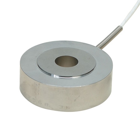
2" OD Through-Hole, Compression Load Cells

2,000 lbf, ±0.5%, Linearity, 2 mV/V Output, Cable, 0.500" ID, 0.63" Height

$898.38

Item# LC8200-500-2K

Volume discounts available
Volume Discount Schedule
Quantity Price each
1-9 $898.38
10-24 $853.46
25-49 $835.49
50-99 $799.56
100+ $781.59

In stock

Lead Time (If not in stock): 4 weeks
2,000 lbf, ±0.5%, Linearity, 2 mV/V Output, Cable, 0.500" ID, 0.63" Height LC8200-500-2K LC8200-500-2K
  • 5 Point NIST Traceable Calibration with
    59 kOhm Shunt Cal Data
  • Low Profile
  • All Stainless Steel Construction
  • Rugged Industrial Design

LC8200-500-2K Model Options

View all models

Edit these specs to order a different model. Not all combinations are valid. Options compatible with previous selections will be in bold.

*Highlighted options are not compatible. Please select a different combination.

Weight Capacity
Through hole (ID)/ Threaded hole dimension
Height
Measurement Units
Force Direction
Linearity
Electrical Output (Nominal)
OD
Connection Type
Cable Length


  • Input Resistance 360 Ω minimum
  • Accuracy Value 0.5
  • Linearity ±0.5% FSO
  • Load Cell Material 17-4 PH stainless steel
  • Maximum Ambient Temperature 121 {C} (250 {F})
  • Maximum Compensation Temperature 71 {C} (160 {F})
  • Measurement Type Load
  • Output Resistance 350 ±5 Ω
  • Minimum Compensation Temperature 16 {C} (60 {F})
  • Number of Conductors 4
  • Repeatability ±0.1% FSO
  • Safe Overload 150% of Capacity
  • Ultimate Overload 300% of Capacity
  • Temperature Effects Zero: ±0.009% FSO/°C
  • Zero Balance ±2.0% FSO
  • Style Through Hole
SPECIFICATIONS
Output: 2 mV/V nominal
Input: 10 Vdc (15V max)
Linearity: ± 0.5% FSO
Repeatability: ± 0.1% FSO
Zero Balance: ±2.0% FSO
Operating Temp Range: -54 to 121°C (-65 to 250°F)
Compensated Temp Range: 16 to 71°C (60 to 160°F)
Thermal Effects:
   Zero: ±0.009% FSO/°C
   Span: ±0.036% rdg/°C
Safe Overload: 150% of capacity
Ultimate Overload: 300% of capacity
Deflection: 0.076 mm (0.003") nominal
Input Resistance: 360 ? minimum
Output Resistance: 350 ±5 ?
Construction: 17-4 PH stainless steel
Electrical: 1.5 m (5') 4-conductor shielded cable
loading all models
loading all reviews
Rated 4 out of 5 by from Fixture Required to Avoid Damage The load cell worked well. My one complaint is that the friction from the nut rotating caused the steel plate we had on the outside to rotate, which in turn caused the load cell to rotate - damaging it's wire. It's easily addressed by either having a fixture, or at the very least having a handle welded to the nut-side plate so it can be held. Lesson learned.
Date published: 2018-06-05
  • y_2025, m_1, d_21, h_6
  • bvseo_bulk, prod_bvrr, vn_bulk_3.0.42
  • cp_1, bvpage1
  • co_hasreviews, tv_0, tr_1
  • loc_en_US, sid_LC8200-500-2K, prod, sort_[SortEntry(order=HELPFULNESS, direction=DESCENDING), SortEntry(order=POSITIVE_FEEDBACK, direction=DESCENDING), SortEntry(order=SUBMISSION_TIME, direction=DESCENDING)]
  • clientName_omega
  • bvseo_sdk, java_sdk, bvseo-4.0.0
  • CLOUD, getReviews, 4ms
  • REVIEWS, PRODUCT
loading all QA

Is the load cell have Integrated Electronics Piezo-Electric device?

Asked by: Mechman
This is not a piezoelectric device. Internal circuit is a 350 ohm full strain gage bridge. It is piezoresistive.
Answered by: Applicatrions Engineer JK
Date published: 2021-03-12

If the load to the rim of the sensor is not evenly contacted, will it cause foce inaccuracy? Is the result similar to normal solid axial style?

Asked by: JoeGM
Thank you for your inquire. Correct Because of the uneven surface there will be a offset . How much is hard to tell. After time you may also get a zero shift.
Answered by: application engineer je
Date published: 2022-07-01

What's the gage factor on the strain gauge?

Asked by: Anonymous
Thank you for your inquire. These sensors use 350 ohm full bridge
Answered by: application engineer je
Date published: 2022-02-15

Is this a full bridge sensor or do we need to complete the bridge with our data acquisition module?

Asked by: MECHA MAN
Yes this load cell is a full bridge configuration. No bridge completion required.
Answered by: JKengineer
Date published: 2021-03-12

What are the dimensions of the loading surfaces - OD of smaller diameter loading surface and ID of larger diameter loading surface?

Asked by: Andy2
A detailed control drawing for the LC8200 Series load cell is available upon request from our applications engineering group. Please email a request to pressure@omega.com and we will email you a copy.
Answered by: Applicatrions Engineer JK
Date published: 2024-10-14

Is this compatible with the vishay DAQ PN mm120-001496?

Asked by: Anthony N
Thank you for your inquire. The load cell will put out a linear milli volt per volt output with a 10 volt excitation. As Long as the device will except this output it should be compatible.
Answered by: application engineer je
Date published: 2022-02-01

i plan on using my own output recording device, what is 2 mV/V mean? is V some form of weight such as kg or lbs? if V is volts, do you have a conversion chart that converts volts to kg?

Asked by: cheesehead
2mV/V is output sensitivity of the load cell. The means that for every volt excitation power you supply to the load cell you will see a nominal 2 mV output at the full force load applied to the load cell. If you apply the nominal excitation of 10VDC to the load cell you will see a nominal output signal of 0 to 20 mVDC over the load range on the load cell. Each load cell is supplied with a NIST traceable calibration report that tell you the exact mV/V sensitivity of that load cell
Answered by: Applicatrions Engineer JK
Date published: 2020-01-14

Is there a minimum clearance in the ID nominal & tolerances to fit an object of the named diameter? For example, if the ID on a ".675 ID" sensor has an effective min/max of .685"-.700", a perfect .675" cylinder fits w/ at least .010" diametrical clearance

Asked by: CTUS
Tolerances for the dimensions on the LC8200 Series are +/- 0.005". A unit with a indicated bore I.D. of 0.625" would have bore tolerance of 0.620" to 0.630"
Answered by: JK Applications Engineer
Date published: 2024-06-17
  • y_2025, m_1, d_21, h_6CST
  • bvseo_bulk, prod_bvqa, vn_bulk_3.0.42
  • cp_1, bvpage1
  • co_hasquestionsanswers, tq_9
  • loc_en_US, sid_LC8200-500-2K, prod, sort_[SortEntry(order=NUM_ANSWERS, direction=DESCENDING)]
  • clientName_omega
  • bvseo_sdk, java_sdk, bvseo-4.0.0
  • CLOUD, getContent, 25ms
  • QUESTIONS, PRODUCT

Related Categories

en-US
en
Save Configuration