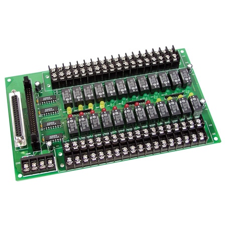
The OME-DB-24R consists of 24 form C, electromechanical relays for efficient switching of load by programmed control. The contact of each relay can control a 0.5 A /110 V load or 1 A/24 Vdc. The relay is energized by applying a 5 V signal to the appropriate relay channel on the 50-pin OPTO-22 compatible connector or 37-pin D-Sub connector. Twenty-four enunciator LED’s, one for each relay, light when their associated relay is activated. To avoid overloading your PC ’s power supply, this board needs a +12 Vdc or +24 Vdc external power supply.
Specifications Relay Type: 24 form C SPDT Nominal Load: 0.5 A @120 Vac,1A @24 Vdc Maximum Switching Power: 60 VA,24 W Maximum Switching Voltage: 120 Vac,60 Vdc Maximum Switching Current: 1A Life Expectancy: mechanical (2 x 10⁷), electrical (2 x 10⁵) Time Value: operate (6 ms) Control Logic: input TTL high (+5 V)current, relay on Power Consumption: +12 V @528 mA max; +5 V @150 mA max Dimensions: 132 H x 225 mm W (8.1 x 4.5') Operating Temperature: 0 to 60°C (32 to 140°F) Storage Temperature: -20 to 70°C (-4 to 158°F) Humidity: 5 to 90% RH non-condensing Connector: OME-DB-24, one 50-pin header; OME-DB-24RD, one 50-pin header and one 37-pin D-sub connector
On page 26 of the manual, the numbering on the right side of the 37-pin D-sub connector seems non-standard. Should standard D-sub numbering (1-19, bottom to top) be used?
Asked by: P126
Thank you for your question. We will require more information to help on this question, please email the DAS team at DAS@OMEGA.COM”
Answered by: Application Engineer PV
Date published: 2021-09-30
Do you offer a ACAD download of the 24-Channel Relay Output Board?
Asked by: Ron T
Thank you for your question. We do not provide a Cad drawing just dimensions in the manual you can download from the website.
Answered by: Cheetah
Date published: 2021-02-05
The manual doesn't provide mounting hole spacing, only outer board dimensions. Can you provide the hole spacing since there are no CAD models?
Asked by: dstix747
Thank you for your questions. Diameter is 4mm for the holes. Spacing is 210mm and 122mm.
Answered by: DAS Engineer
Date published: 2024-05-21
Does this board require an external 5V power supply in addition to 12/24V? I am unsure if the +5V lines shown on page 26 of the manual are for supply or reference.
Asked by: P126
Hello
Regarding your question, if you are referring to the +5VDC on the board, that is to specifically power up the relays on the board, whereas the 12VDC/24VDC connection is to power up the board itself.